The Printed Circuit Board Assembly (PCBA) industry is a cornerstone of modern electronics manufacturing, requiring a thorough understanding of components, their symbols, and packaging types. Two essential elements that frequently arise in PCBA projects are the LDR (Light Dependent Resistor) symbol and the DIP (Dual In-line Package) These aspects not only influence the functionality of a circuit but also dictate assembly processes, testing, and quality assurance.
In this article, we’ll explore these concepts, their applications, and their significance in PCBA manufacturing.
Understanding the LDR Symbol
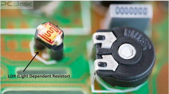
An LDR, also known as a photoresistor, is a variable resistor that changes its resistance based on the amount of light incident on it. When the light intensity increases, the resistance of the LDR decreases, and vice versa. This property makes LDRs invaluable in circuits that require light sensitivity, such as:
- Automatic lighting systems (e.g., streetlights and home automation)
- Light meters used in photography or industrial applications
- Security systems with light-based triggers
- Solar tracking systems to optimize panel orientation
LDR Symbol in Schematics
In schematic diagrams, the LDR is represented by a symbol resembling a resistor, with diagonal arrows pointing towards it. These arrows indicate the component’s responsiveness to light. Understanding this symbol is essential for PCB designers, as it guides proper placement and connections during the design and assembly phases.
For PCBA manufacturers, identifying the LDR symbol ensures that the correct component is sourced and placed precisely on the PCB. Misinterpretation of symbols can lead to functionality issues, delays, and added costs. In automated assembly environments, ensuring proper recognition of such symbols also supports efficient programming of pick-and-place machines.
Challenges in PCBA with LDRs
Although LDRs are straightforward components, they come with unique challenges in the PCBA process:
- Light Shielding: During testing and assembly, stray light can affect the component’s performance. Proper handling, shielding, and controlled environments are required.
- Calibration: Circuits involving LDRs often require post-assembly calibration to ensure they function as intended under specific lighting conditions.
- Soldering Sensitivity: Excessive heat during soldering may damage the LDR, necessitating precise temperature controls in the soldering process.
By addressing these challenges, manufacturers can optimize assembly efficiency and reduce defects in LDR-based products.
What is a DIP Package?
The Dual In-line Package (DIP) is one of the most recognizable and widely used types of component packaging in PCB design. It features two rows of pins that extend downward and fit into corresponding holes on the PCB. This through-hole design provides secure electrical and mechanical connections, making DIP components popular for robust and repairable assemblies.
Common Applications
DIP packages are often used for components such as:
- Microcontrollers (e.g., Arduino chips)
- Logic ICs
- Operational amplifiers
- Memory modules
- Sensors and other discrete devices
Despite the rise of Surface-Mount Devices (SMDs), DIP packages remain relevant, especially in:
- Prototyping and testing, where components need to be swapped or reprogrammed easily.
- Repairable systems, where through-hole components are easier to replace than surface-mount counterparts.
- Educational purposes, as DIPs are more beginner-friendly due to their size and simplicity.
DIP in PCBA Manufacturing
The PCBA process for DIP components involves distinct steps, including hole drilling, pin insertion, and wave or hand soldering. While DIP components are larger and may require more PCB real estate compared to SMDs, they offer several advantages:
- Ease of Assembly: DIPs are relatively simple to handle, even for manual soldering processes.
- Durability: The mechanical strength of through-hole connections makes DIP components ideal for applications subject to vibration or stress.
- Testing: DIP ICs can be easily removed and replaced during debugging or testing, reducing development time.
Automation Challenges
While DIP components are advantageous in many ways, their assembly may require specialized machinery for automation, such as wave soldering systems or automatic insertion machines. Compared to SMDs, DIPs can slightly increase production time due to additional drilling and soldering steps.
LDR and DIP Package in PCBA: Synergy and Importance
The combination of components like LDRs and packaging types like DIPs illustrates the diversity of the PCBA industry. LDRs are often used in DIP packages, simplifying their integration into circuits while maintaining ease of handling. Their synergy is particularly evident in products designed for light-sensitive applications where durability and flexibility are key.
For instance, an automated streetlight controller may use an LDR housed in a DIP package. This setup ensures the LDR can be easily assembled, replaced, or tested, making it suitable for both small-scale prototyping and mass production.
Design Considerations
PCB designers working with LDRs and DIP packages must balance several factors:
1 .Board Size: DIP components consume more space, requiring careful layout planning.
- Signal Integrity: Through-hole leads can create inductive effects that impact high-speed signals.
- Thermal Management: Components like LDRs can be heat-sensitive, necessitating proper thermal handling during soldering.
Cost Implications
While DIP components are generally cost-effective for prototyping and small-scale production, they may increase assembly costs for high-volume manufacturing. Designers must weigh these factors against the specific requirements of the application.
Conclusion
The LDR symbol and DIP package are fundamental concepts in the PCBA industry, each contributing uniquely to circuit design and assembly processes. LDRs bring versatility and functionality to light-sensitive applications, while DIP packages provide durability, ease of handling, and repairability. Together, they offer a reliable solution for various electronic systems, from consumer products to industrial controls.
For manufacturers, mastering the nuances of these components ensures smoother workflows, higher-quality products, and greater customer satisfaction. Whether you’re designing for prototyping or large-scale production, understanding these elements is crucial for success in the ever-evolving PCBA industry.