If you’re towing a trailer, understanding the 7 pin trailer wiring diagram is crucial. Whether you’re hauling a boat, RV, or utility trailer, a proper electrical connection ensures that the lights, brakes, and other functions of the trailer work seamlessly with your towing vehicle. The 7-pin trailer wiring system is the most common setup for larger trailers that require multiple electrical functions, such as brake lights, turn signals, and trailer brakes.
In this article, we will break down the components of the 7-pin trailer wiring diagram, explain each pin’s function, and guide you on how to properly wire your trailer. By understanding this system, you can ensure a safe and reliable connection between your towing vehicle and trailer.
What is a 7 Pin Trailer Wiring System?
The Basics of Trailer Wiring
A trailer’s wiring system is designed to connect its electrical functions to the towing vehicle, enabling lights and other essential systems to work properly. A 7-pin trailer wiring system typically serves larger trailers, such as RVs, horse trailers, or utility trailers. It’s equipped with seven pins (or connectors) that link the various electrical functions of the trailer to your vehicle.
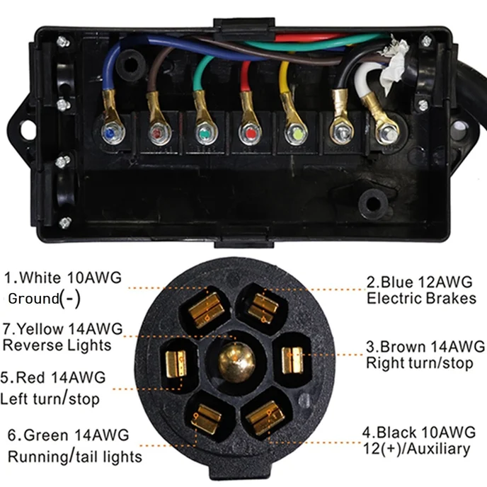
Each pin has a specific function, and the connection is typically made via a 7-way plug, which is attached to the back of your vehicle. The plug then connects to a corresponding socket on the trailer. Understanding how each pin works is essential to ensuring everything, from lights to brakes, functions as it should.
Types of Trailer Wiring Systems
Trailer wiring systems typically come in 4-pin, 5-pin, and 7-pin configurations. While 4-pin systems are common for smaller trailers, 7-pin systems are more prevalent for larger trailers with complex electrical needs. The 7-pin wiring system can handle a variety of functions, including:
-
Brake lights
-
Turn signals
-
Running lights
-
Trailer brakes
-
Grounding
The 7-pin system is often required by law in many regions for trailers that exceed certain weight limits, ensuring safety by supporting trailer brake systems and other critical functions.
The 7 Pin Trailer Wiring Diagram: Pin by Pin Breakdown
Ground (White Wire)
Function of the Ground Pin
The ground wire (often marked as Pin 1) is one of the most crucial components of the 7-pin trailer wiring diagram. It provides the return path for the electrical current and helps complete the circuit, ensuring the safe operation of all the electrical systems. Without a properly grounded connection, your trailer’s lights and braking systems may malfunction.
-
Wire Color: White
-
Location on Connector: Pin 1 (usually located at the top of the connector)
-
Purpose: The ground wire prevents electrical shorts by allowing the current to flow back into the towing vehicle’s electrical system. This pin is connected to the trailer’s metal frame.
Left Turn Signal / Brake Light (Yellow Wire)
Function of Left Turn Signal and Brake Light Pin
Pin 2 controls the left turn signal and brake light of the trailer. When you activate the left turn signal or press the brake pedal, this pin sends the corresponding electrical signal to the trailer’s lights. This ensures that the trailer’s brake lights and turn signals operate in sync with the towing vehicle.
-
Wire Color: Yellow
-
Location on Connector: Pin 2
-
Purpose: It connects to the left side of the trailer, ensuring that both the turn signal and brake light functions are in place.
Right Turn Signal / Brake Light (Green Wire)
Function of Right Turn Signal and Brake Light Pin
Much like Pin 2, Pin 3 operates the right turn signal and right brake light of the trailer. When the right turn signal is activated or the brakes are applied, this pin activates the corresponding lights on the trailer, ensuring that the trailer’s lighting system mirrors the actions of the vehicle.
-
Wire Color: Green
-
Location on Connector: Pin 3
-
Purpose: It connects to the right side of the trailer, allowing for the operation of the right turn signal and brake light.
Tail/Running Lights (Brown Wire)
Function of the Tail/Running Lights Pin
Pin 4 is responsible for controlling the tail and running lights of the trailer. These lights are required for visibility when driving at night or in low-light conditions, ensuring that the trailer is visible to other drivers on the road.
-
Wire Color: Brown
-
Location on Connector: Pin 4
-
Purpose: It connects to the trailer’s tail lights and is activated when the vehicle’s headlights are turned on, allowing the trailer to be visible at night.
Electric Brakes (Blue Wire)
Function of the Electric Brakes Pin
Pin 5 is essential for trailers with electric brakes. It carries the signal from the towing vehicle’s brake controller to the trailer’s braking system. This ensures that the trailer’s brakes engage in sync with the vehicle’s braking system, improving safety when towing heavy loads.
-
Wire Color: Blue
-
Location on Connector: Pin 5
-
Purpose: It’s used for electric brake control, activating the trailer’s braking system in response to the vehicle’s brake signals.
Backup Lights (Purple Wire)
Function of the Backup Lights Pin
Pin 6 controls the backup lights on the trailer. When you put the vehicle in reverse, the backup lights on the trailer are activated, helping you see behind the trailer and making your movements more visible to others.
-
Wire Color: Purple
-
Location on Connector: Pin 6
-
Purpose: It connects to the trailer’s backup lights, ensuring that they light up when the vehicle is in reverse.
Auxiliary Power (Black Wire)
Function of the Auxiliary Power Pin
Pin 7 provides auxiliary power to the trailer. This power is used to run other accessories, such as interior lights, air conditioning, or other electrical components inside the trailer. The auxiliary power can also be used to charge the trailer’s battery, ensuring that the trailer’s systems remain operational while on the road.
-
Wire Color: Black
-
Location on Connector: Pin 7
-
Purpose: It delivers 12V power to the trailer, allowing for a variety of functions that require electricity.
How to Wire a 7 Pin Trailer Connection
Tools You Will Need
Before starting the installation of a 7-pin trailer wiring system, gather the following tools:
-
7-pin trailer plug and socket
-
Electrical wire (appropriate gauge for each pin)
-
Wire connectors
-
Soldering iron (optional)
-
Electrical tape
-
Crimping tool
-
Multimeter (for testing the wiring)
Step-by-Step Wiring Process
Preparing the Wires
Start by cutting the electrical wire to the appropriate lengths for each function. You’ll need to measure out enough wire to reach from the vehicle’s tow connection to the trailer’s lights and braking system.
-
Pin 1 (Ground): Attach the white wire to the metal frame of the trailer to ensure a solid ground connection.
-
Pin 2 & 3 (Left and Right Turn Signals): Use yellow wire for the left turn signal and green wire for the right turn signal. Route the wires to the appropriate side of the trailer’s rear lights.
-
Pin 4 (Tail Lights): The brown wire connects to the trailer’s tail light circuit.
-
Pin 5 (Electric Brakes): Run the blue wire to the electric brake controller inside the trailer.
-
Pin 6 (Backup Lights): Attach the purple wire to the trailer’s backup light circuit.
-
Pin 7 (Auxiliary Power): Use black wire to deliver power to the trailer’s auxiliary system.
Connecting the Wires to the Trailer Plug
Once you have the appropriate wires, connect each one to the corresponding terminal on the 7-pin trailer plug. Ensure that you secure each wire with the appropriate crimp connector or solder it for a stronger, more reliable connection.
Securing the Wires
Ensure that the wires are routed neatly and secured with zip ties to prevent them from hanging loosely and getting damaged while driving. Check for any sharp edges or points that could cause wear on the wires.
Testing the System
Once everything is connected, plug the 7-pin connector into the vehicle’s tow connection. Test each electrical function to ensure it works correctly. Use a multimeter to verify that each pin is receiving the correct voltage and that the trailer lights and brakes respond appropriately.
Common Problems with 7 Pin Trailer Wiring
Corroded Pins or Connectors
Corrosion is a common issue with trailer wiring, particularly if the trailer is used in wet or salty environments. Make sure to inspect your connections regularly and clean them with a wire brush or contact cleaner to ensure a solid electrical connection.
Loose Connections
Loose or improperly connected wires can cause electrical failures, such as lights not working or brakes failing to engage. Always double-check the connections and ensure the wires are securely fastened.
Damaged Wires
Physical damage to the wiring, such as cuts, abrasions, or frays, can disrupt the electrical system and lead to malfunctioning trailer lights or brakes. Inspect your wiring for any visible damage and replace any worn or damaged sections of wire.
Conclusion: Understanding Your 7 Pin Trailer Wiring Diagram
A 7 pin trailer wiring diagram is essential for ensuring that all of your trailer’s electrical components are properly connected and functioning. By understanding the roles of each pin and how to wire the system correctly, you can ensure that your trailer’s lights, brakes, and other functions work seamlessly with your towing vehicle. Always use the appropriate wire gauges, follow the wiring diagram carefully, and perform regular maintenance checks to keep your trailer’s electrical system in good working order.
With this knowledge, you can confidently set up and maintain your 7-pin trailer wiring system, ensuring safe and effective towing on the road.